Biomagnetic separation when chemiluminescence immunoassay (CLIA) IVD kit developed and produced five key Mistakes
Chemiluminescent immunoassay (CLIA) combines highly sensitive chemiluminescence technology with highly specific immunological reactions to establish chemiluminescence immunoassays. CLIA has the characteristics of high sensitivity, strong specificity, wide linear range, easy operation and low cost of use. CLIA has a wide range of applications, detecting antigens, haptens and antibodies of different molecular sizes, as well as nucleic acid probes. Due to its advantages, the number of in vitro diagnostic tests based on this technology is increasing. And whenever a Chemiluminescence Analyzer is installed in a hospital or diagnostic laboratory, the demand for its corresponding kit will likely reach thousands of units per day.
Â
As a result, the demand for CLIA IVD kits has begun to soar, but early small-scale production, pure manual operations, and simple quality control methods have been unable to cope with the need for mass production. How to ensure consistency between batches; how to ensure the stability of quality after scale-up of production; how to ensure the effectiveness of the final application of the finished product (finally only use no more than a few hundred microliters in the analyzer) into the production of CLIA IVD kit key. In more than a decade of development, we have identified five key misconceptions in the biomagnetic separation process. These misunderstandings are easily overlooked but often delay the progress of the project, causing significant economic losses and sometimes even putting production at risk. Therefore, correctly mastering the technical information of magnetic separation is the key to ensuring the success of product development and production.
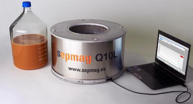
Figure 1: New biomagnetic separation system
How to describe a biomagnetic separation process?
When a new CLIA-IVD kit is transferred from the development phase to the production phase, all production operating parameters need to be re-adjusted to accommodate new production volumes and processing volumes. The specifications, buffers and coatings of biomarkers benefit from the experience gained in the production of non-magnetic kits. Coupling beads of antibodies and magnetic beads are very similar to colloidal gold or latex particles, but the use of magnetic separation in the cleaning process is quite different from other non-CLIA-IVD kits.
Â
Although the use of biomagnetic separation in the separation phase of production by the CLIA kit seems to be an obvious choice, there are still some problems in the practice. The first is to describe the entire process itself. When communicating with IVD kit manufacturers, they found that in terms of biomagnetic separation, they often mentioned the following aspects:
Â
- Separation time: The time from which the solid phase is separated from the buffer system.
- Bead Loss: The maximum value of magnetic beads (and coupled biomarkers) lost during production.
- Batch processing volume: The batch size to be processed, and even in some cases the processing volume is flexible.
- To avoid irreversible aggregation: In the process of production, if irreversible magnetic bead aggregation occurs, it needs to be resuspended in various ways. After suspension, it must be checked whether it is handled properly. Because each kit (in milliliters) requires the same properties, incorrect resuspension processing can increase the difference between batches.
However, these are all "functional" parameters, they are the result of magnetic separation and not a factor affecting the separation process. What are the parameters that are really missing but define the entire separation process throughout the biomagnetic separation process?
Â
The key parameter in the biomagnetic separation process is the magnetic force . The magnetic beads move at a specific speed, which is due to the competition between the magnetic force and the resistance, which is caused by the viscosity of the buffer.
Â
In selecting the magnetic beads, the user is very concerned about whether the "correct" magnetic beads are selected. Assuming that the appropriate biomarkers and the perfect coupling/coating method have been selected, then the user selecting the "correct" bead should have the following characteristics:
Â
1 ) High recovery / fast separation , matching time in the analytical equipment, magnetic separation speed is fast enough, there is not a large number of magnetic beads and coupled biomarker loss during mass production?
2 ) Without aggregation problems , the magnetic beads can be easily resuspended and suspended. Even if the beads are aggregated, they can be recovered by several additional sonication steps. (but this is difficult to control and operate during mass production)
3 ) Low batch-to-batch variation, each batch aliquot (usually less than milliliters) and production batch (upgrade) must be consistent. If not, will the difference affect the results given by the analyzer?
Â
What if the above requirements are not met?
For the most deficient magnetic separation results, the most common response of kit manufacturers is that the choice of magnetic beads is “wrongâ€. Then the production company contacts the magnetic bead supplier (or substitute supplier) for long-term discussion on the magnetic beads, re-examines the coating method, etc. If it falls into this stage, the development and launch of new products will be seriously affected, and the progress will be greatly delayed.
Â
| Tip: If the biomarker is well coupled to the magnetic beads, it will be an expensive and time consuming process to replace the magnetic beads in case of problems , and the problem will still not be solved effectively ! |
Manufacturers should get rid of the "correct" and "wrong" magnetic beads, and focus on the biomagnetic separation equipment and equipment. By comparing the following figures, we can see that the same suspended magnetic beads will show completely different conditions under the action of different biomagnetic separators.

Figure 2: Separating the same magnetic bead suspension with two magnets
Figure 2 shows that the magnetic beads processed by the traditional magnetic frame (blue) on the left are slowly separated. This means a longer time to complete the separation or to withstand the loss of higher magnetic beads and biomarkers. However, if you wait for a longer separation time to avoid loss, some of the beads will be affected by the irreversible aggregation problem, because the first separated magnetic beads (close to the wall of the bottle) are subjected to very strong magnetic forces to squeeze the beads. together. If at this separation step, we do not consider the influence of the separation device, only judge from the performance of the separation of the magnetic beads, then we will get a wrong conclusion: we must replace the other magnetic beads to solve the problem. At the same time, we can observe from Figure 2 that the same magnetic bead suspension passed through the advanced biomagnetic separation device (orange on the right) and we can see that the separation is completely different. The magnetic beads are quickly separated at the same speed, and due to the uniform magnetic force, the attached magnetic beads are subjected to a gentle magnetic force in a shorter time, eliminating the risk of irreversible aggregation.
Â
Advice for the CLIA-IVD kit manufacturer:
Rather than constantly considering the replacement of magnetic beads, we should more quickly and economically dig out the problems and factors derived from magnetic separation equipment. When the magnetic separation device is adjusted, if the magnetic beads can be normally suspended, the doubts about the magnetic beads will not be broken, and there is no need to reconstruct the operation process of the coating.
Â
In the previous section we discussed why it is a big misunderstanding that the magnetic bead is a problem when it is separated. The main cause of the problem in the separation process is the magnetic magnet instead of the magnetic bead. However, it is only known that the magnetic force should be adjusted without knowing how to properly select the magnet.
Â
The second common misconception is to assume that increasing the magnet will increase the magnetic force. However, the magnetic force does not depend on the magnetic field, but on the magnetic field gradient. If the magnet is small, the magnetic field becomes uniform and the magnetic force is greatly weakened. As a result, the separation time is too long or higher. If the magnet is large, the magnetic field and magnetic field gradients decay rapidly with distance, and the magnetic force is not enough to attract the magnetic beads that are furthest away. Worse, the magnetic force close to the magnet is too large, causing irreversible magnetic beads to collect.
Â
Under the premise of using the same number of permanent magnets, compare the large ordinary magnets with the advanced biomagnetic separation system. The optimum magnetic range is to ensure that the beads can be quickly separated and reduced in loss, while providing a gentle retention of the attached beads, ensuring that the beads are attracted to the walls of the vessel without irreversible accumulation. As shown on the left side of the figure below, the cyan portion indicates the area of ​​the best magnetic force. The magnetic beads suspended under optimal separation conditions are only a small fraction of the magnetic beads. The magnetic force increases rapidly near the magnet, so the risk of irreversible aggregation of the magnetic beads becomes higher. The long separation process exacerbates this risk. In contrast, advanced biomagnetic separation systems produce a uniform magnetic force by adjusting the magnetic field distribution. This means that the magnetic force in the entire work area is the same. Magnetic beads on the walls away from the vessel are subjected to a stronger magnetic force than ordinary magnets. The magnetic beads move faster, reducing separation time and ensuring complete recovery of magnetic beads and coupled biomarkers. In the adherent retention zone, the magnetic force remains the same, and the gentle magnetic force ensures that the magnetic beads can be attached to the retention zone without irreversible aggregation.
Â
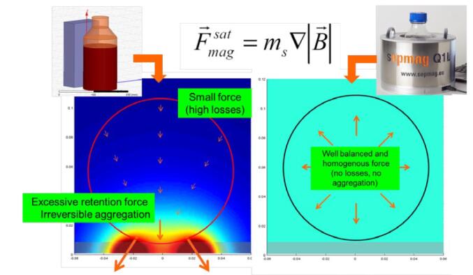
Figure 3: Magnetic force map, conventional magnet (left), advanced from biomagnetic separation system (right)
| Tip: Traditional permanent magnets can only produce a very low magnetic field gradient, usually only a few millimeters away from the magnet, and very far from the magnetic force. This means a large loss of magnetic beads and protein/biomarkers. Even if the separation operation is long, the magnetic beads can hardly be completely separated. |
So, how to avoid the misunderstanding 2: choose a larger magnet to avoid the loss of separation? We should use magnetic rather than magnetic fields to measure the separation system, and the magnetic force needs to be properly balanced, because excessive magnetic force can cause irreversible aggregation problems. The most ideal magnetic separation system provides the right magnetic field for both the farthest area and the reserved area (adherent area).
Â
The third common misunderstanding involves the verification of the separation process.
In many cases, biomagnetic separation processes are often verified by a specified separation time. The problem with this verification method is that the verification is associated with a specific magnetic field profile and container size, and the separation time is only the result of velocity (proportional to magnetic force) and the distance traveled by the magnetic beads. Separation time cannot be used to describe magnetic bead separation. Process conditions.
Â
In order to better verify the separation process, we need additional information to describe this separation process. One method is to optically monitor the change in permeability of the suspension (the suspension is turbid at the beginning of the separation and the liquid phase tends to penetrate once the magnetic beads begin to separate). In this way, the verification can be observed and recorded not only in the end phase (separation time) but throughout the biological separation process.
Â
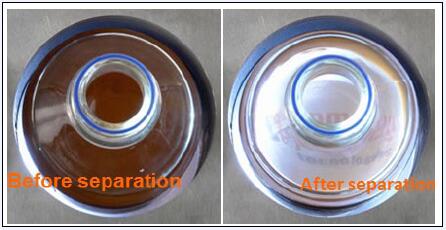
Figure 4: Turbidity comparison of magnetic separation suspensions, initial phase (left), end phase (right)
If the biomagnetic separation system has well-defined conditions (ie, uniform magnetic force), the curve of opacity over time will usually form an S shape. The two-parameter index P and time t50 defining the curve respectively reflect the difference between the steepness of the curve and the maximum and minimum opacity at which the separation time reaches half. These two parameters depend on some characteristics (diameter, magnetic content %, magnetic material) and suspension (buffer viscosity, magnetic bead concentration, etc.) derived from the magnetic beads. Since the shape of the measurement curve is affected by all of these parameters, monitoring can establish specific reference data and curves for different separation processes. When the magnetic conditions are fixed, the verification of the same separation process should follow the corresponding reference curve.
Â
When the entire process can be monitored and not only judged by separation time alone, quality problems in the process can be discovered more quickly. By comparing the deviations from the reference curve, it is possible to reveal production problems (aggregation, incorrect magnetic bead characteristics, magnetic bead concentration, etc.) in numerous biomagnetic separation processes. This means that production personnel can take corrective actions earlier, thereby reducing costs.
Â
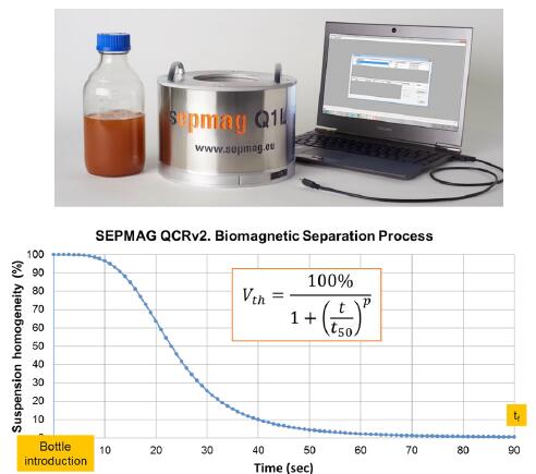
Figure 5: Typical shape separation curve (S type) obtained by establishing a biomagnetic separation process and optical monitoring
So, how can we avoid misunderstanding 3: Define the entire separation process purely by separating time? By using a uniform magnetic force, all the beads are separated and monitored under the same conditions. Through real-time monitoring, in addition to reducing the differences between kit batches, these steps also improve the quality control of the process and help to identify production issues in a timely manner.
Â
When developing a chemiluminescent kit, the initial focus of the manufacturer is often on biomarkers such as coupling to magnetic beads. Biomagnetic separation conditions are often ignored. In the early stages of development, the separation process is usually carried out on a small scale using a common magnetic frame. When the separation conditions are not well defined during the amplification process, the magnetic force of the magnetic beads in the development stage is completely different from the new system after amplification. This problem is the main cause of the loss of magnetic beads and raw materials and the irreversible aggregation of magnetic beads. factor. This requires an expensive and time consuming reengineering process to address these issues in order to achieve a material loss and magnetic bead aggregation level low enough to provide a cost effective and efficient production solution.
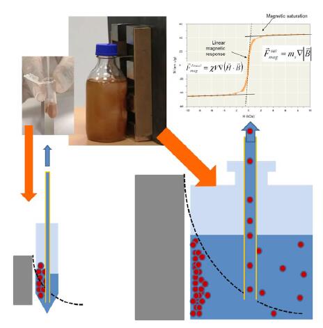
Figure 6. Schematic diagram of magnetic separation and liquid exchange on a small (left) and large (right) non-uniform magnetic separation frame. The black dotted line indicates the magnitude of the magnetic force. The magnetic force near the magnet is large and the distal end is reduced.
In small-scale separation operations, small ranges are prone to high magnetic field gradients. Even if not all of the magnetic beads are magnetically saturated, the separation time is short due to the short moving distance of the magnetic beads and does not cause too much loss or irreversible aggregation. However, in large-scale separation, due to the non-uniform magnetic force, it will cause greater loss (larger distance and lower magnetic force) and multiplication of separation time. In large-sized containers, the greater magnetic force near the magnet will increase the risk of irreversible aggregation. The portion away from the magnet is separated by a weak magnetic force. In contrast, uniform magnetic separation conditions avoid these problems and make it easier to scale up when production occurs. When a uniform gradient magnetic field is used, the magnetic force can remain unchanged even if the size becomes large.
Â
In order to avoid the influence of amplification on magnetic separation, it is especially important to directly copy the original parameters in the process of amplification and separation, avoiding the loss of magnetic beads and avoiding the accumulation of irreversible magnetic beads. Manufacturers can provide stable magnetic force and can be amplified during the initial development period. The development of separator equipment. Just as the SEPMAG® system provides stable magnetic force and convenient amplification support, clear process conditions can be determined from the initial small volume development period, and after the development period to the scale-up production, the production company does not need to re-adjust the process (as shown in Figure 7). , greatly reducing the time and resources required from R&D to production and subsequent amplification.
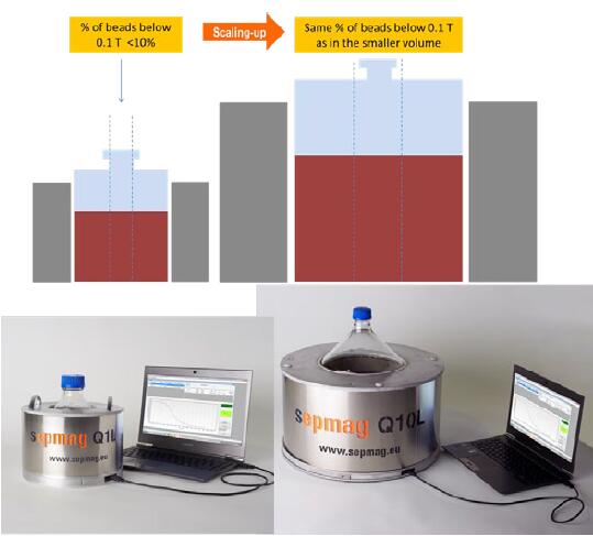
Figure 7. Advanced biomagnetic separator provides uniform magnetic field to support different sizes of magnification
The above four points are all related to the production process. However, even with a perfect repeatability and efficient production process, the hidden safety risks to operators and equipment in the production of IVD manufacturing companies must be avoided.
Â
The application of magnets on a scale can create high-risk accidents. Magnets attract ferromagnetic objects, including other magnets, scissors, screwdrivers, or other magnetic objects. A potential hazard occurs when the body or device is exposed between the magnet and the object being attracted, and the greater the volume of the magnet, the greater the risk to the user. For people with implanted pacemakers or other implantable devices, the risk is equally high: the magnetic field can interfere with the device and cause a malfunction. This is also the reason why serious danger signs are posted near the hospital's MRI area.
Â
Safety risks not only pose a risk of injury to the user, but laboratory equipment also has the risk of being affected by magnetic fields, especially items including magnetic recording media, such as credit cards and/or corporate magnetic cards. Computers, cell phones, and hard drives can also lose information, and many lab electronics can be affected.
Â
| Set the safe operating area according to the magnetic field range. Clear out the hazardous area (magnetic field > 3mT, 30 Gauss), which hides the risk of mechanical accidents caused by the attraction between the magnet and the magnetic object. There is also a need to clear out a larger warning zone (magnetic field > 0.5mT or 5 Gauss) because it has the risk of eliminating magnetic recording media and disturbing pacemaker implant devices. |
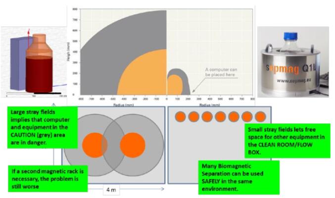
Figure 8: Operational safety zone settings, conventional magnet (left), advanced biomagnetic separator (right), hazardous area (orange), warning zone (gray)
These safety settings are very important, as shown in Figure 8. If the magnetic separator is not designed for special magnetic safety handling, stray magnetic fields will mean that computers and other electronic equipment may be exposed to hazardous areas. Therefore, in the danger zone, a large enough space should be cleared out and other equipment should be avoided. If you need to put a few magnetic separation devices in the same room, the problem will become more serious. Conversely, if the design of the biomagnetic separation system reduces the stray magnetic field, the magnetic separation system will greatly reduce the impact on the outside world while reducing the area requirement. As shown in Figure 8, the area required for placement of several advanced biomagnetic separation systems is less than the area required for a conventional magnetic separation frame.
Â
Therefore, how to solve the misunderstanding 5: The magnetic field operating conditions have not taken appropriate safety measures? First, safety practices should be established and the safe operating range should be calculated: set the alert area and the hazardous area. Secondly, in addition to considering the separation performance of the magnetic separator/rack, attention should also be paid to the stray magnetic field generated by the magnetic separator/rack. Whenever possible, choose a biomagnetic separation system with a small stray magnetic field or a safe magnetic separation device . For example, SEPMAG®'s advanced magnetic separation system can be placed next to the computer with special design and protects the operator from the dangers of using traditional large magnets. This reduces the risk of accidents while reducing the danger zone and leaving more room for other equipment.
Â
To learn more about how SEPMAG® can help you optimize your biomagnetic separation process ,
Please visit : or click to download SEPMAG Ebooks 
Technical support: 400-9910-165 / 028-85568133
The lock channel is one of the most important thing for greenhouse, it can lock the film ,shading net ,insect net .
It is hot galvanized or aluminum material.
We have different thickness.
Welcome to contact us
Lock Channel,Greenhouse Lock Channel,Channel Lock,greenhouse profile
JIANGSU SKYPLAN GREENHOUSE TECHNOLOGY CO.,LTD , https://www.spgreenhouse.com